
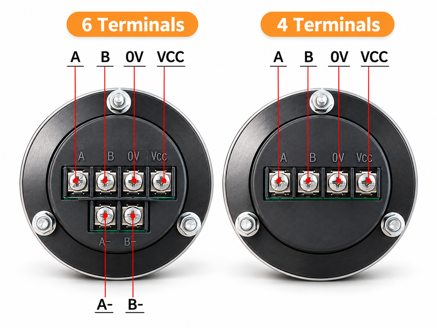
Four-terminal and six-terminal MPG handwheel configurations differ in the connections available at the handwheel. The four-terminal arrangement has VCC, 0V, A and B markings. The six-terminal arrangement adds A- and B- complementary channel markings. Those labels are a starting point for an electrical comparison, rather than a complete wiring diagram.
This guide explains terminal functions and the information to gather before connecting a selected version to a controller or receiving board. It does not establish a universal pinout: physical positions, electrical ratings and receiver requirements must be checked against the actual equipment documentation.
Reading the terminal markings
The handwheel terminal block includes power connections as well as signal channels. Four or six refers to terminal count, not the number of controlled axes. Axis selection belongs to the controller or separate panel controls.
| Terminal marking | Function to identify | Available on |
|---|---|---|
| VCC | Positive supply connection | Four and six terminals |
| 0V | Supply return / reference connection | Four and six terminals |
| A | Rotary signal channel A | Four and six terminals |
| B | Rotary signal channel B | Four and six terminals |
| A- | Complementary channel corresponding to A | Six terminals |
| B- | Complementary channel corresponding to B | Six terminals |
This table lists functions, not left-to-right positions. Read the markings on the actual unit and match them to its drawing. A physical layout must specify the viewing direction, such as the rear terminal side, before it can be used to locate a connection. Do not transfer positions from a front view or a photograph taken from another angle.
The technical details show the listed terminal arrangements. Where a label or view is unclear, obtain clarification before using it as a connection instruction.
Confirming supply separately from signal level
VCC and 0V supply the handwheel. The listed supply/PPR combinations are 5 V DC with 100 PPR, 12 V DC with 25 PPR, and 24 V DC with 100 PPR. These are separate configurations, not a continuous supply range for one unit. Applying another voltage does not convert a unit to a different PPR.
Confirm the selected version’s supply requirement and polarity before connection. The available machine supply must meet that requirement under the intended installation conditions. Do not assume that a receiving board’s input-voltage description is also a suitable power-source specification for the handwheel.
Supply voltage and output signal level are separate quantities. A 24 V supply marking does not establish that A and B switch at 24 V, just as a 5 V supply does not establish a particular output circuit. Compatibility assessment uses the selected version’s documented output circuit and signal levels.
Understanding A and B channels
In quadrature operation, A and B provide related waveforms offset by approximately 90 electrical degrees. A suitable receiver uses their sequence to determine rotation direction and counts the accepted events. Electrical degrees describe the phase within a signal cycle, not the mechanical angle of a quarter revolution.
The controller’s decoding and increment settings determine how accepted counts become a movement request. PPR, decoded counts and mechanical detents are different quantities. A 100 PPR label does not prove 100 clicks per revolution or a fixed travel distance. The handwheel basics guide includes conditional ×1, ×2 and ×4 count examples.
Direction also depends on the controller convention, configuration and wiring. If the indicated direction is unexpected, follow the machine’s documented diagnostic and commissioning procedure. Check the labels and direction settings before changing connections. Exchanging A and B is not a universal first instruction, especially when the interface includes complementary pairs or other wiring requirements.
What A- and B- identify
A- and B- are marked as complementary counterparts of A and B. The suffix does not identify another supply return, and it must not be confused with the separate 0V terminal. Their presence describes available channels without establishing all electrical properties of those channels.
In a compatible differential interface, a receiver compares the signals in each pair, such as A against A-. That operating principle can reduce sensitivity to some interference when the driver, receiver, cabling and installation are designed to work together. It does not follow that every six-terminal handwheel meets a particular electrical standard.
The six-terminal marking alone does not confirm RS-422 compliance, a line-driver circuit, allowable cable length or an interference-performance guarantee. Those require the actual output and receiver specifications. Likewise, leaving A- and B- unconnected does not establish compatibility with a single-ended input; use only a connection arrangement supported for both devices.
Comparing the output circuit with the receiving input
The handwheel output circuit describes how its signal terminals drive the connection. The receiving input describes what the board can accept. Compare them as separate specifications rather than assuming that similar labels prove a match.
Handwheel information to confirm
Obtain the selected version’s output circuit, signal levels, loading limits and relevant timing information. Confirm supply requirements and the physical terminal arrangement as well. Channel labels and terminal count do not fill gaps in those specifications.
The current configuration choices establish diameter, finish, supply/PPR combination and terminal count. They should not be treated as confirmation of an output topology that has not been documented for the selected version.
Receiving board information to collect
Use the receiving board or module manufacturer’s documentation for input format, voltage thresholds, reference connections, permissible frequency and minimum pulse width. Include any specified filtering, termination or bias requirements that apply to that input.
The handwheel order information cannot substitute for the board documentation. Record the exact board model alongside the controller model, because different receiving modules can have different requirements. If an interface adapter is proposed, its suitability needs confirmed electrical information on both sides.
Preparing the connection and cable route
Prepare a connection schedule that maps confirmed handwheel labels to documented receiver terminals. Record the drawing views and the versions of the equipment being compared. Follow the machine’s maintenance procedure when inspecting or altering the installed wiring.
Cable selection, pair arrangement, shield bonding and reference connections should follow the equipment’s electrical and EMC documentation. Shield bonding at one end or both ends can depend on the installation design; this guide does not prescribe a universal direction. Consider nearby power equipment and the documented routing requirements when planning the cable path.
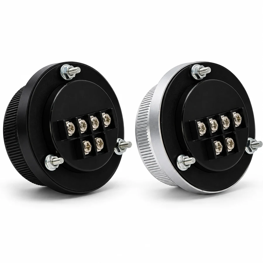
Check the mounting details for rear clearance, access to terminal markings and conductor space. A connection that fits electrically still needs a mechanically suitable enclosure and service access.
Information to send before choosing a configuration
For a configuration inquiry, provide the controller model, receiving board model and relevant input documentation. Include the old part’s label and terminal photographs for replacement work, along with any confirmed output requirements.
Select the preferred 60 mm or 80 mm diameter, black or silver anodized aluminum alloy body and dial, supply/PPR combination, terminal count and quantity from the available configurations. Keep any unresolved interface details visible in the inquiry. Finalize the connection using confirmed specifications for both devices and verify the response through the machine’s documented commissioning process.